Voltage Drop Calculator
Calculate voltage drop and percent drop for copper or aluminum wire in DC, single-phase and three-phase circuits, by AWG or mm².
Quick answer
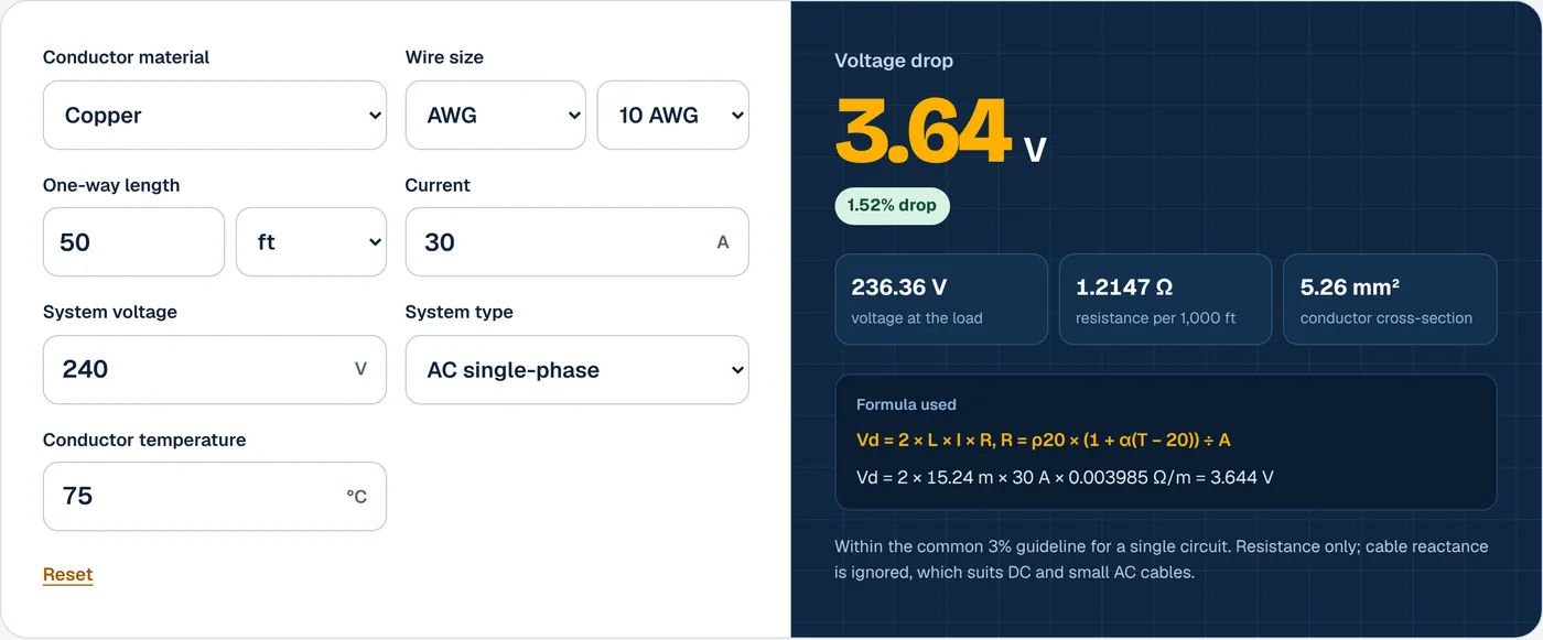
Voltage drop is the voltage lost in a cable’s resistance. For DC and single-phase circuits, Vd = 2 × L × I × R, where L is the one-way length and R is the resistance per meter. For three-phase, Vd = √3 × L × I × R. Divide Vd by the supply voltage for the percentage. The NEC recommends 3% per branch circuit.
How to use the voltage drop calculator
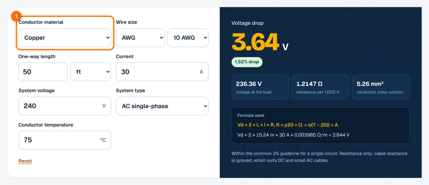
- Choose the conductor material. Select copper or aluminum. Aluminum has higher resistance, so it drops more voltage for the same size.
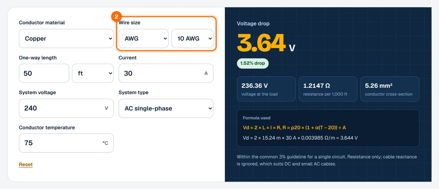
- Choose the wire size. Enter the gauge in AWG (for example 10 AWG or 2/0) or the cross-section in mm² (for example 4 mm² or 16 mm²).
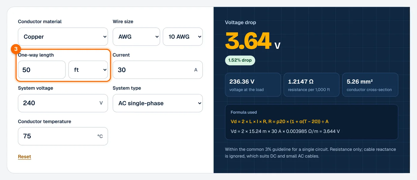
- Enter the one-way length. Measure the cable route from source to load, in feet or meters, including rises and slack. Do not double it.
- Enter the current. Use the load current in amps. For solar strings, use the string’s operating current. For battery cables, use the inverter’s maximum DC input current.
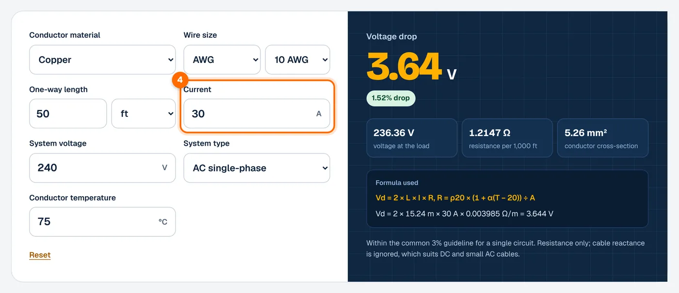
- Enter the system voltage. Use the nominal voltage at the source, such as 12 V, 24 V or 48 V DC, 120 V or 240 V single-phase, or 208 V, 400 V or 480 V three-phase line-to-line.
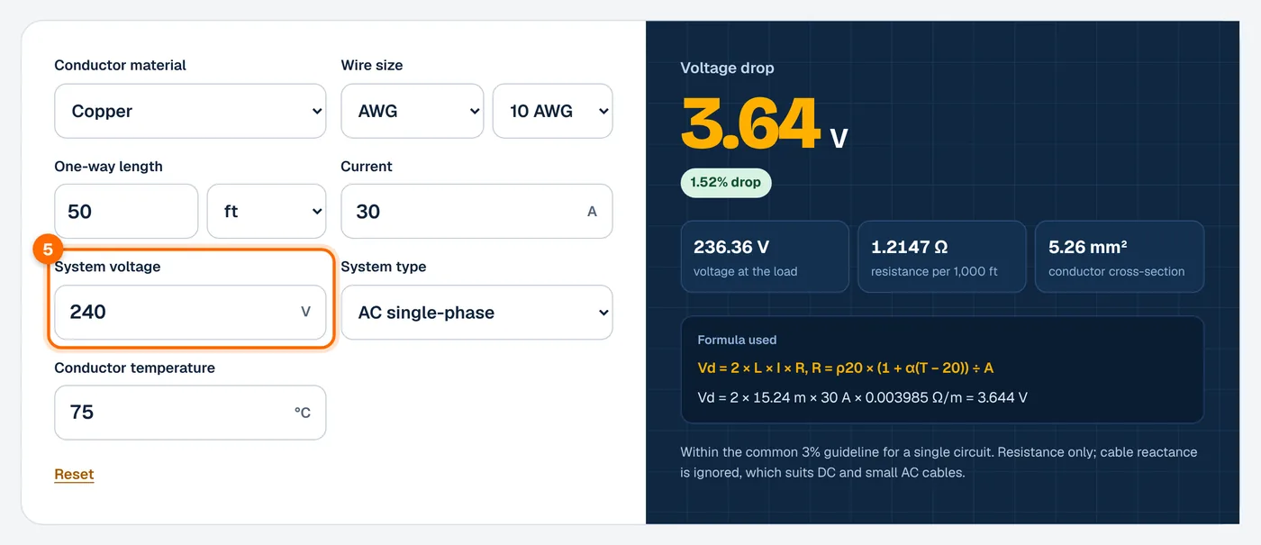
- Choose the system type. Select DC, single-phase AC or three-phase AC.
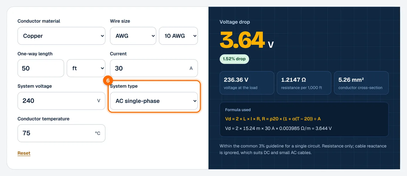
- Set the conductor temperature. The default is 75 °C (167 °F). A hotter conductor has higher resistance and more voltage drop.
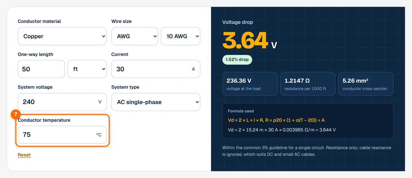
- Read the result. The calculator shows the voltage drop in volts, the percentage drop and the voltage left at the load.
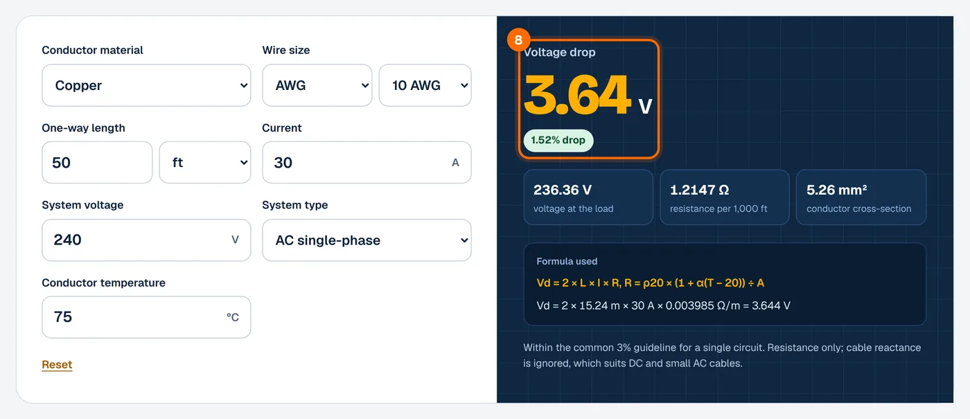
Voltage drop formula
Step 1: Cross-section from AWG
Here n is the AWG number. For 1/0 use n = 0, for 2/0 use n = −1, and so on. If you enter mm², the calculator uses that area directly.
Step 2: Resistance per meter at temperature
Step 3: Voltage drop
Where:
- d is the conductor diameter in mm, and A is its cross-section in mm².
- ρ20 is resistivity at 20 °C: 0.017241 Ω·mm²/m for copper and 0.028264 Ω·mm²/m for aluminum.
- α is the temperature coefficient: 0.00393 per °C for copper and 0.00403 per °C for aluminum.
- T is the conductor temperature in °C.
- R is the resistance of one conductor in ohms per meter.
- L is the one-way cable length in meters (1 ft = 0.3048 m).
- I is the current in amps, and V is the system voltage.
- Vd is the voltage drop in volts.
The factor 2 counts the outgoing and return conductors. In a balanced three-phase circuit, the factor √3 (about 1.732) replaces it. The method uses resistance only and ignores reactance, so it is most accurate for DC circuits such as solar strings and battery cables and for smaller AC cables. For large AC feeders, reactance adds some extra drop.
Worked examples
Example 1: 48 V battery cable, 2 AWG copper, 3 m, 100 A
Area: d = 0.127 × 9234/39 = 6.544 mm, so A = 33.63 mm².
About 0.37 V is lost between the battery and the inverter, leaving about 47.6 V at full load.
Example 2: 240 V single-phase, 10 AWG copper, 100 ft, 24 A
Length: 100 ft × 0.3048 = 30.48 m. Area: d = 2.588 mm, so A = 5.261 mm².
The load sees about 234.2 V. This is within the NEC’s 3% branch-circuit recommendation.
Example 3: 400 V three-phase, 4 mm² copper, 50 m, 20 A
This is within the BS 7671 guidance of 5% for non-lighting circuits on a public supply.
Voltage drop limits and copper resistance
Recommended and required limits
| Rule | Applies to | Limit | Status |
|---|---|---|---|
| NEC 210.19(A) informational note | Branch circuit to farthest outlet | 3% | Recommendation |
| NEC 210.19(A) and 215.2(A) informational notes | Feeder plus branch circuit combined | 5% | Recommendation |
| NEC 647.4(D) | Sensitive electronic equipment: branch circuit / feeder plus branch | 1.5% / 2.5% | Requirement |
| BS 7671 Appendix 4 (public LV supply) | Lighting | 3% | Guidance |
| BS 7671 Appendix 4 (public LV supply) | Other uses | 5% | Guidance |
Copper resistance at 75 °C
Computed with the method above (ρ20 = 0.017241 Ω·mm²/m, α = 0.00393 per °C). Values are per single conductor and rounded.
| Size | Area (mm²) | Ω per 1,000 ft | Ω per km |
|---|---|---|---|
| 14 AWG | 2.08 | 3.071 | 10.08 |
| 12 AWG | 3.31 | 1.932 | 6.337 |
| 10 AWG | 5.26 | 1.215 | 3.985 |
| 8 AWG | 8.37 | 0.764 | 2.506 |
| 6 AWG | 13.30 | 0.480 | 1.576 |
| 4 AWG | 21.15 | 0.302 | 0.991 |
| 2 AWG | 33.63 | 0.190 | 0.623 |
| 1/0 AWG | 53.48 | 0.119 | 0.392 |
| 2/0 AWG | 67.43 | 0.095 | 0.311 |
| 2.5 mm² | 2.5 | 2.556 | 8.387 |
| 4 mm² | 4 | 1.598 | 5.242 |
| 6 mm² | 6 | 1.065 | 3.495 |
| 10 mm² | 10 | 0.639 | 2.097 |
| 16 mm² | 16 | 0.399 | 1.310 |
| 25 mm² | 25 | 0.256 | 0.839 |
| 35 mm² | 35 | 0.183 | 0.599 |
For aluminum at the same size and temperature, resistance is about 1.65 times the copper value.
What affects the result
Cable length
Voltage drop rises in direct proportion to length. Doubling the run from 50 ft to 100 ft doubles the drop.
Wire size
Resistance falls as the cross-section grows. Each step of three AWG sizes roughly halves the area and doubles the resistance. Going from 10 AWG to 8 AWG cuts the drop by about 37%.
Current and system voltage
Drop in volts rises with current. The percentage drop also depends on the system voltage, so low-voltage DC systems are most sensitive. A 1 V loss is about 8% of a 12 V system but under 1% of a 240 V circuit. This is a main reason solar battery banks move from 12 V to 24 V or 48 V as they grow.
Conductor temperature
Copper resistance rises about 0.39% per °C. At 75 °C, copper has about 22% more resistance than at 20 °C. Hot attics, rooftop conduit and fully loaded cables run warmer, so a 20 °C figure understates the real drop.
Frequently asked questions
What is an acceptable voltage drop?
In the US, NEC informational notes recommend no more than 3% on a branch circuit and 5% for the feeder and branch circuit combined. In the UK, BS 7671 Appendix 4 gives 3% for lighting and 5% for other uses on installations fed from the public low-voltage supply. Lower is better for efficiency.
Is the NEC 3% rule mandatory?
In most cases, no. The 3% and 5% figures appear in informational notes, which are advisory. The NEC does make voltage drop mandatory in a few places, such as Article 647 for sensitive electronic equipment, which limits branch circuits to 1.5% and feeder plus branch to 2.5%. Local rules or designers may set stricter limits.
Should I enter the one-way or round-trip length?
Enter the one-way length from the source to the load. The calculator multiplies by 2 for DC and single-phase circuits to include the return conductor, and by √3 for three-phase circuits. Entering the round-trip length by mistake would double the calculated result.
Why use 75 °C for conductor temperature?
Conductors carrying load run warmer than room temperature, and resistance rises with heat. A 75 °C default matches a common conductor temperature rating and gives a conservative result. If you know the cable runs cooler, lower the temperature and the calculated drop will fall slightly.
Does this work for solar panel strings?
Yes. Choose DC, enter the string’s operating current and voltage, and the one-way distance from the array to the inverter or charge controller. Because the method ignores reactance, it is well suited to DC solar wiring, charge controller runs and battery cables.