Voltage Divider Calculator
Find a divider's output voltage, or the R2 for a target Vout, with load effects and the nearest E12 and E24 resistors.
Quick answer
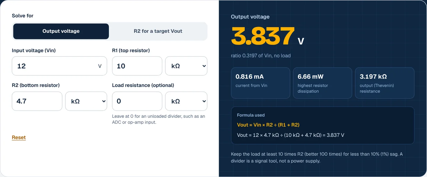
A voltage divider’s output is Vout = Vin × R2 ÷ (R1 + R2). With 12 V in, R1 = 10 kΩ and R2 = 4.7 kΩ, the output is 12 × 4.7 ÷ 14.7 = 3.837 V. To hit a target, solve R2 = R1 × Vout ÷ (Vin − Vout): 5 V to 3.3 V with a 10 kΩ R1 needs 19.41 kΩ, so the nearest E24 value is 20 kΩ.
How to use the voltage divider calculator
- Choose what to solve for. Pick output voltage to check an existing pair of resistors. Pick R2 for a target Vout to design a divider for a sensor, ADC input or battery monitor.

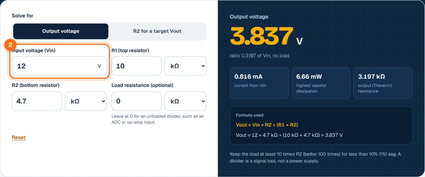
- Enter the input voltage. Type the voltage across the whole divider, such as 5 V, 12 V or a 14.4 V charging battery.
- Enter the resistors or the target. Enter R1 (the top resistor, from Vin to the output) and R2 (the bottom resistor, from the output to ground) with their units. In R2 mode, enter R1 and the output voltage you want.
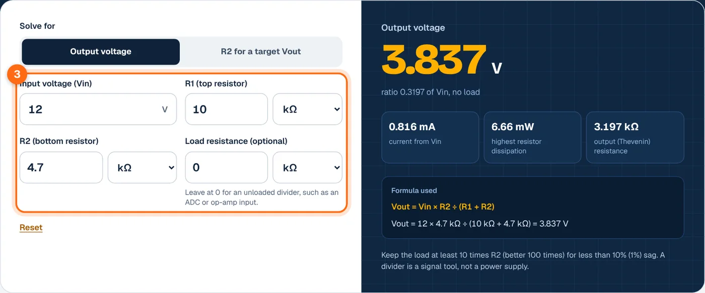
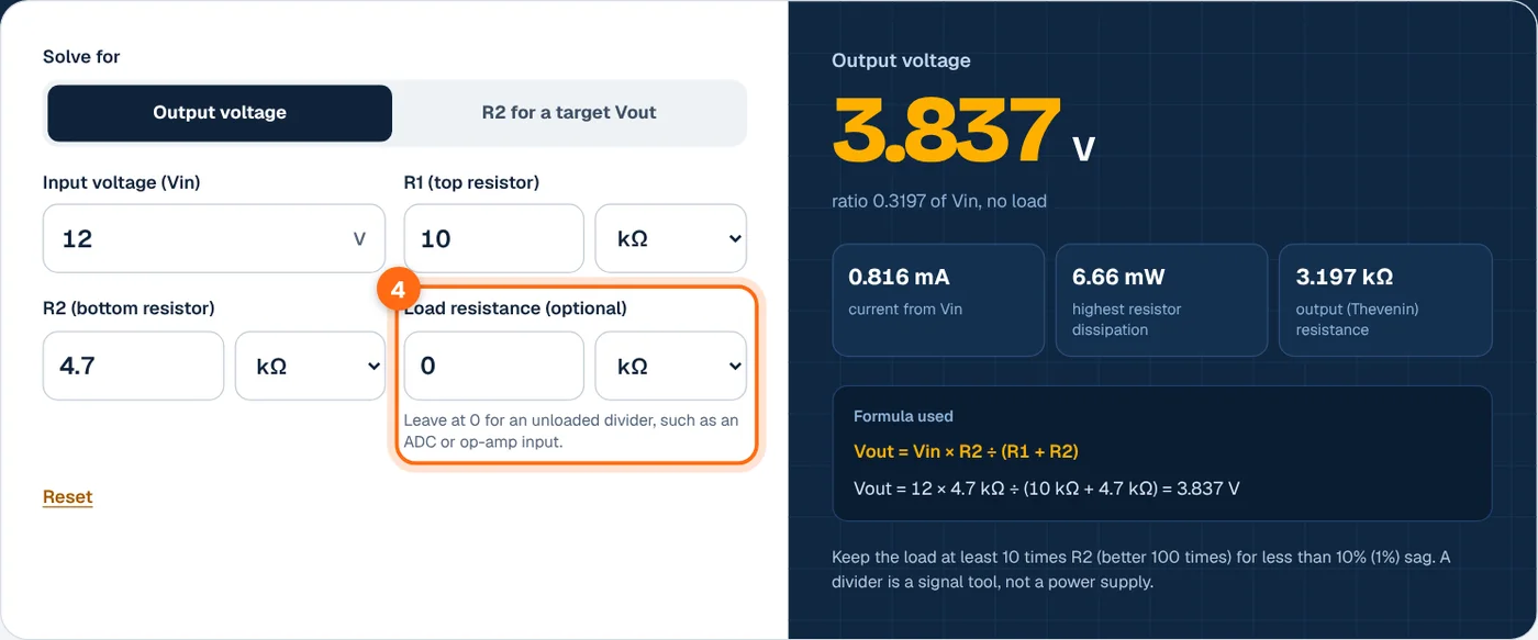
- Add the load, if any. Enter the resistance of whatever connects to the output. Leave 0 for high-impedance inputs such as a microcontroller ADC or op-amp.
- Read the result. The large number is Vout or the required R2. The cards show divider current, resistor dissipation and output resistance, or the nearest E12 and E24 resistors with the voltage each one actually gives.

Voltage divider formula
Two resistors in series share the input voltage in proportion to their resistance. The same current flows through both, so by Ohm’s law the voltage across R2 is its share of the total. See the HyperPhysics voltage divider page for the derivation.
Unloaded output
Solving for R2
Loaded output
Divider current and output resistance
Where:
- Vin is the voltage across the full divider and Vout the voltage across R2.
- R1 is the top resistor and R2 the bottom resistor.
- RL is the load connected across R2. R2′ is R2 in parallel with RL.
- Rout is the Thevenin output resistance, which sets how much a load pulls the voltage down.
Worked examples
Example 1: 12 V with 10 kΩ and 4.7 kΩ
This is the default. R1 dissipates (0.816 mA)² × 10 kΩ = 6.66 mW, so any small resistor is fine. The output resistance is 3.197 kΩ.
Example 2: the same divider with a 10 kΩ load
The load pulls the output down 24%. A 470 kΩ load would only drop it to 3.811 V, under 1%. That is the 10× and 100× rule in action.
Example 3: 5 V logic down to 3.3 V
The nearest E24 value, 20 kΩ, gives 5 × 20 ÷ 30 = 3.333 V. The nearest E12 value, 18 kΩ, gives 3.214 V. Both are inside typical 3.3 V input limits.
Common divider designs with standard resistors
R2 values for R1 = 10 kΩ, the nearest E24 resistor and the output it actually produces. Standard values follow the IEC 60063 preferred number series.
| Vin | Target Vout | Exact R2 | Nearest E24 | Actual Vout |
|---|---|---|---|---|
| 3.3 V | 1.8 V | 12 kΩ | 12 kΩ | 1.8 V |
| 5 V | 3.3 V | 19.41 kΩ | 20 kΩ | 3.333 V |
| 9 V | 5 V | 12.5 kΩ | 13 kΩ | 5.087 V |
| 12 V | 5 V | 7.143 kΩ | 7.5 kΩ | 5.143 V |
| 12 V | 3.3 V | 3.793 kΩ | 3.9 kΩ | 3.367 V |
| 14.4 V | 3.3 V | 2.973 kΩ | 3 kΩ | 3.323 V |
| 24 V | 5 V | 2.632 kΩ | 2.7 kΩ | 5.102 V |
| 48 V | 3.3 V | 738.3 Ω | 750 Ω | 3.349 V |
What affects the result
Load resistance
Any load in parallel with R2 lowers the output. Keep the load at least 10 times the output resistance for under about 10% error, or 100 times for under 1%. If the load is heavy or changes, buffer the output with an op-amp follower.
Resistor tolerance
E12 parts are typically 10% tolerance and E24 parts 5%, though 1% parts are common in E24 values. Two 5% resistors can shift the output several percent. Use 1% or 0.1% resistors for measurement circuits.
Resistor values and current
Low values waste power and load the source. High values save power but raise output resistance and pick up noise, and an ADC’s sampling capacitor may not charge fully. Totals of 10 kΩ to 100 kΩ suit most microcontroller inputs.
Not a power supply
A divider cannot supply a motor, LED strip or other real load, because its output voltage changes with load current and the resistors waste power as heat. For that, use a regulator or a DC-DC converter. Check current draw with the Ohm’s law calculator.
Frequently asked questions
How does a voltage divider work?
Two resistors in series carry the same current, so each drops a voltage in proportion to its resistance. The output is taken across the bottom resistor, giving Vout = Vin × R2 ÷ (R1 + R2). Equal resistors halve the voltage. A larger R2 gives a larger share of the input.
How do I choose resistor values for a voltage divider?
Pick R1 first, often 10 kΩ, then compute R2 = R1 × Vout ÷ (Vin − Vout). Round R2 to the nearest standard value and recheck the output. The calculator suggests the nearest E12 and E24 resistors and shows the exact voltage each one produces.
Can I use a voltage divider to step down 12 V to 5 V for a device?
Only for a signal, such as a sensor or an ADC input that draws microamps. A device that draws real current will pull the output down and the resistors will waste power. For powering devices, use a linear regulator or a buck converter rated for the load current.
Why is my divider output lower than calculated?
The usual cause is loading. Whatever is connected to the output sits in parallel with R2 and reduces the effective resistance. A multimeter’s input resistance, often 10 MΩ, can also load high-value dividers. Enter the load resistance in the calculator to see the loaded voltage.
How do I measure a battery voltage with a microcontroller?
Scale the highest battery voltage below the ADC reference. For a 14.4 V charging battery and a 3.3 V ADC, use R1 = 10 kΩ and R2 = 3 kΩ for 3.323 V at full charge. Multiply the ADC reading by (R1 + R2) ÷ R2 in code to recover the battery voltage.