10 Gauge Wire Amp Rating: How Many Amps Can 10 AWG Carry?

Short answer
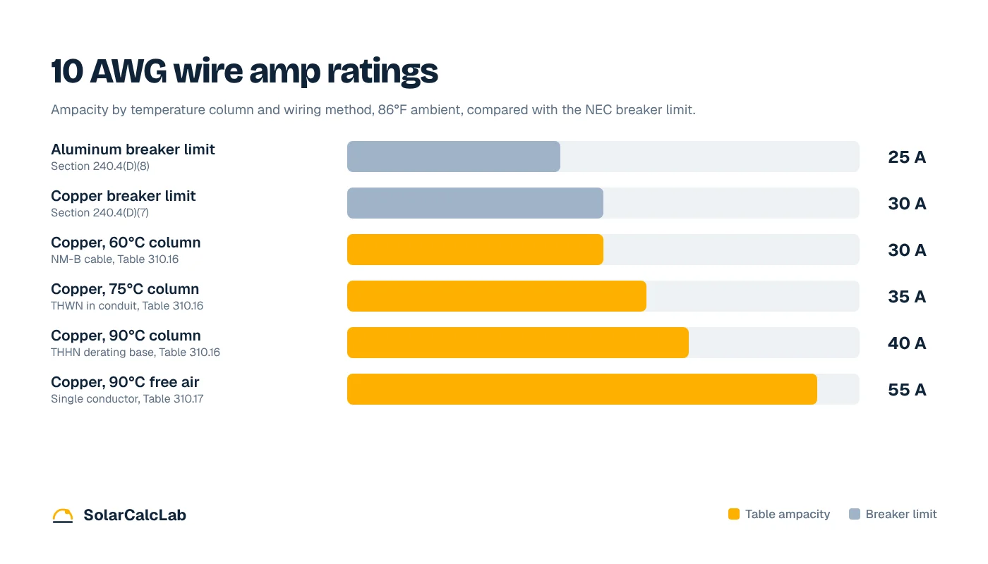
Under NEC Table 310.16, 10 AWG copper wire is rated 30 amps at 60°C, 35 amps at 75°C and 40 amps at 90°C. Section 240.4(D) caps the breaker at 30 amps for most circuits, so in a house 10 gauge copper is a 30 amp wire. That gives 7,200 watts at 240 V, or 5,760 watts for a continuous load. 10 AWG aluminum is limited to a 25 amp breaker.
Ten gauge wire is what you pull for the bigger 30 amp loads in a home: electric dryers, water heaters, window and central AC units, and many Level 2 EV chargers. The 10 gauge wire amp rating is confusing because charts list three numbers for one conductor, and the breaker size comes from a different rule.
Values below come from Tables 310.16 and 310.17 and Section 240.4 of NFPA 70, the National Electrical Code.
10 AWG wire ampacity chart
Ampacity is the current a conductor can carry continuously without exceeding its insulation temperature rating. Raceway rows assume three or fewer current-carrying conductors and 86°F (30°C) ambient. The free air rows apply to single conductors not in a raceway, such as PV wire under a solar array.
| 10 AWG conductor | 60°C (140°F) | 75°C (167°F) | 90°C (194°F) |
|---|---|---|---|
| Copper, raceway or cable (310.16) | 30 A | 35 A | 40 A |
| Aluminum, raceway or cable (310.16) | 25 A | 30 A | 35 A |
| Copper, single conductor in free air (310.17) | 40 A | 50 A | 55 A |
| Aluminum, single conductor in free air (310.17) | 35 A | 40 A | 45 A |
| Maximum breaker, Section 240.4(D) | 30 A copper, 25 A aluminum | ||
Solid and stranded 10 AWG carry the same rating. The copper values match the ampacity tables that wire makers publish, such as the Cerrowire ampacity chart.
Why 10 gauge wire is a 30 amp wire
If 10 AWG THHN is rated 40 amps at 90°C, why not use it on a 40 amp breaker? Because Section 240.4(D) sets separate limits for small conductors. Unless a specific exception applies, the overcurrent protection for 10 AWG copper must not exceed 30 amps, and for 10 AWG aluminum or copper-clad aluminum it must not exceed 25 amps.
The 35 and 40 amp values still matter as the starting point for derating, covered below. The common cases:
- 10/2 or 10/3 NM-B (Romex): Section 334.80 holds NM cable to the 60°C column, which is exactly 30 amps. It goes on a 30 amp breaker.
- 10 AWG THHN or THWN-2 in conduit: rated 35 amps at the 75°C terminals most breakers carry, but still protected at 30 amps.
- 10 AWG aluminum: uncommon in branch circuits today, and limited to a 25 amp breaker.
When 10 AWG can go on a bigger breaker
Section 240.4(G) lists equipment where the small conductor rule does not apply because the equipment has its own overload protection. The two you will meet most are motor circuits under Article 430 and air conditioning and refrigeration equipment under Article 440. A condenser nameplate that reads “Minimum circuit ampacity 26 A, Maximum overcurrent protection 40 A” can be wired with 10 AWG copper on a 40 amp breaker, because the wire only has to meet the 26 A minimum circuit ampacity.
For receptacles, dryers, water heaters and EV chargers, the answer stays the same: 10 gauge copper means a 30 amp breaker or smaller. For a 40 amp circuit, see what size wire a 40 amp breaker needs, and for 50 to 65 amp loads see the 6 AWG wire amp rating guide.
How many watts can 10 gauge wire handle?
Watts equal volts times amps. Use the breaker size, not the table ampacity, and keep continuous loads (three hours or more) at 80% of the breaker.
240 V, 30 A breaker: 240 × 30 = 7,200 W maximum, 240 × 24 = 5,760 W continuous
120 V, 30 A breaker: 120 × 30 = 3,600 W maximum, 120 × 24 = 2,880 W continuous
| Circuit | Breaker | Maximum load | Continuous load (80%) |
|---|---|---|---|
| 240 V, 10 AWG copper | 30 A | 7,200 W | 5,760 W |
| 120 V, 10 AWG copper | 30 A | 3,600 W | 2,880 W |
| 240 V, 10 AWG aluminum | 25 A | 6,000 W | 4,800 W |
| 120 V, 10 AWG aluminum | 25 A | 3,000 W | 2,400 W |
Check any appliance against these limits with the watts to amps calculator, or go the other way with the amps to watts calculator.
Common 30 amp loads on 10 gauge wire
Continuous loads are sized at 125% of the load current, the same as keeping them at 80% of the breaker.
| Load | Typical rating | Current at 240 V | Sizing current | Fits 10 AWG, 30 A? |
|---|---|---|---|---|
| Electric dryer (NEMA 14-30 outlet) | 5,600 W | 23.3 A | 23.3 A | Yes |
| Tank water heater, 50 gallon | 4,500 W | 18.8 A | 23.4 A (× 1.25) | Yes |
| Tank water heater | 5,500 W | 22.9 A | 28.6 A (× 1.25) | Yes |
| Level 2 EV charger set to 24 A | 5,760 W | 24.0 A | 30.0 A (× 1.25) | Yes, exactly |
| Level 2 EV charger set to 32 A | 7,680 W | 32.0 A | 40.0 A (× 1.25) | No, use 8 AWG on 40 A |
Section 422.13 treats a storage water heater of 120 gallons or less as a continuous load, and Article 625 does the same for EV chargers. That is why a 32 amp charger, one of the most popular settings, cannot use 10 gauge wire. To see how long a 24 A versus 32 A charger takes to fill your car, use the EV charging time calculator.
Derating 10 AWG for heat and crowded conduit
Table values assume 86°F and three or fewer current-carrying conductors. More conductors in one raceway, or a run through a hot attic, lowers the allowed ampacity under Section 310.15. For THHN you start from the 90°C value of 40 amps.
| Condition (10 AWG copper THHN, 90°C base 40 A) | Factor | Adjusted ampacity | 30 A breaker OK? |
|---|---|---|---|
| 4 to 6 current-carrying conductors in one conduit | 0.80 | 32 A | Yes |
| 7 to 9 current-carrying conductors | 0.70 | 28 A | No |
| Ambient 97°F to 104°F (36°C to 40°C) | 0.91 | 36.4 A | Yes |
| Ambient 115°F to 122°F (46°C to 50°C) | 0.82 | 32.8 A | Yes |
| 106°F to 113°F and 4 to 6 conductors | 0.87 × 0.80 | 27.8 A | No |
Example: 40 A × 0.87 × 0.80 = 27.8 A, which is below 30 A
When the adjusted value falls under 30 amps, drop to a 25 amp breaker, split the conductors into another conduit, or move up to 8 AWG. The next-size-up rule in Section 240.4(B) does not apply to multi-outlet receptacle circuits.
Voltage drop: how far can you run 10 gauge wire?
Ampacity does not account for voltage lost on a long run. An informational note in the NEC suggests keeping branch circuit drop near 3%. Using the resistance of solid uncoated 10 AWG copper from NEC Chapter 9, Table 8 (1.21 ohms per 1,000 feet), a 120 V circuit looks like this:
| One-way distance | 16 A load | 24 A load | 30 A load |
|---|---|---|---|
| 25 ft | 1.0 V (0.8%) | 1.5 V (1.2%) | 1.8 V (1.5%) |
| 50 ft | 1.9 V (1.6%) | 2.9 V (2.4%) | 3.6 V (3.0%) |
| 75 ft | 2.9 V (2.4%) | 4.4 V (3.6%) | 5.4 V (4.5%) |
| 100 ft | 3.9 V (3.2%) | 5.8 V (4.8%) | 7.3 V (6.0%) |
Example: 2 × 50 ft × 24 A × 0.00121 Ω/ft = 2.9 V, or 2.4% of 120 V
At 120 V, 10 AWG copper stays under 3% up to about 62 feet at a 24 A continuous load and about 50 feet at a full 30 A. At 240 V those distances double, to about 124 and 99 feet. For a detached garage or shop further out, go up a size. Test your own run in the voltage drop calculator, or let the wire size calculator pick a gauge that handles ampacity and drop together. For the next size down, compare the 12 gauge wire amp rating.
10 AWG wire in solar and 12 V DC systems
On a low-voltage DC system, voltage drop limits 10 gauge long before ampacity does. A 25 A load 10 feet one way from a 12 V battery on 10 AWG copper loses 2 × 10 × 25 × 0.00121 = 0.61 V. That is 5.0% of 12 V, more than double the 2% to 3% most installers aim for. At 24 V the same 0.61 V is only 2.5%.
On the PV side, 10 AWG PV wire is the standard home run size for residential strings. Section 690.8 sizes PV source circuits at 125% of the module short circuit current, and then another 125% for continuous duty. A module with a 14 A short circuit current gives 14 × 1.25 × 1.25 = 21.9 A, well inside the 55 A free air rating of 10 AWG at 90°C, even after rooftop temperature correction. The solar cable size calculator runs those factors and the voltage drop check in one step.
Installation tips for 10 gauge circuits
- Use 10/3 with ground for dryers and ranges that need a neutral. A modern 4-wire dryer connection needs two hots, a neutral and a separate ground.
- Pull a permit for new 240 V circuits, and hire a licensed electrician if any step is unclear.
Frequently asked questions
How many amps can 10 gauge wire handle?
10 AWG copper is rated 30 amps at 60°C, 35 amps at 75°C and 40 amps at 90°C under NEC Table 310.16. Section 240.4(D) limits the breaker to 30 amps for general circuits, so in practice 10 gauge copper is a 30 amp wire.
Can 10 gauge wire handle 40 amps?
Not on a normal branch circuit. 10 AWG THHN has a 40 amp rating at 90°C, but the NEC caps its breaker at 30 amps. The exceptions are air conditioners and motors, where the nameplate maximum overcurrent protection can allow a 40 amp breaker on 10 AWG.
Is 10 gauge wire good for a 30 amp EV charger?
10 AWG copper on a 30 amp breaker supports an EV charger set to 24 amps, because chargers are continuous loads sized at 125%. A charger set to 32 amps needs a 40 amp circuit and at least 8 AWG copper.
How many watts can 10 gauge wire carry at 240 volts?
On a 30 amp breaker, 10 gauge copper carries up to 7,200 watts at 240 V. For a continuous load lasting three hours or more, keep it at 80%, which is 5,760 watts. At 120 V the limits are 3,600 and 2,880 watts.
What is the amp rating of 10/2 Romex?
10/2 NM-B (Romex) is rated 30 amps. Section 334.80 holds NM cable to the 60°C column of Table 310.16, which is 30 amps for 10 AWG copper, and that matches the 30 amp breaker limit in Section 240.4(D).


